Sunday, July 30, 2017

Off to a Slow Start Again

July 30, 2017

The hot rod project has been on hold since mid-March. The hiatus was due to a number of things. First I helped a friend's sister flip her condo, we were out of the country for a few weeks and to get the car ready to go kart, the rack was being used. Now the hot rod is on the rack and we are starting up again, but have a bit of the summer blahs, so it's slow going. 

Our main job now that it's on the rack, is to button up all the lines (brake, fuel, and electrical) that were too hard to get to on the stand we built. With it all the way up on the rack,  we can really see how things are routed and make sure the lines are secure and routed out of harm's way. For example, we just tightened up the exhaust and it took a while since it touched the frame and would have caused extreme vibrations if we left it routed that way. So we reworked the exhaust so there was some clearance to the frame.

We are in process, but so far we secured the radiator hose, hooked up the emergency brake cables, and routed the oxygen sensors. Plenty more to do while it's up in the air.

very tight but we got it not to touch the frame


The muffler and the heat shield above it


Emergency brake linkage

Thursday, March 16, 2017

Off the Stand and on the Ground

March 16, 2017

After almost a year of having the car being built on a wooden stand, we have it on the ground. 


From now on we will use the hydraulic lift and floor jacks to work on anything under the car. 

Some pictures with my nephew David and his Mom Evie


The car rides really low, the clearance from frame to the ground is just 4.5 inches. It's lower than the 73 corvette David is restoring.

The first time we could look at the engine from above - it fills up the engine compartment!


A few items to close the loop on.

We could not find a way for the rear donor car wheels to fit over the 13 inch rotors and brake calipers, so we went with doughnut spare tires -  a $17 purchase from the pick and pull to be able to roll the car around and use until we figure out the custom wheels and tires we need to order. No sense in getting them now and trying to keep them clean and paint free while we do the body work.

We finally have a solution for the air conditioner compressor. When we moved the engine forward two inches it caused a lot of modifications. For example the motor mounts, driveshaft, exhaust headers - all mentioned in earlier blog posts. The last one we were noodling on was the A/C compressor. Being two inches forward, it is in a tight space and the hard lines could not fit. We could have went with another compressor and mount it somewhere else, but we have little room for an alternative mount and we would have to configure a new serpentine belt. Both more difficult to do vs trying to get the existing one to work. We got lucky and our custom hose shop was able to modify the compressor block with a 90 degree escape which now just fits. So we avoided changing the serpentine belt and mounting a new A/C compressor.


Old compressor block


New modified compressor block


Installed - just need to reinstall the exhaust header.


We also needed to get an extender for the Oxygen sensor on the driver’s side and we added a  FORD MUSTANG SVE MIL ELIMINATOR (O2 SENSOR SIMULATOR) for the rear Oxygen sensors so we could fool the computer for any check engine faults – we did this because we want to run a wireless OBD connector to a tablet to display key engine performance and be our check engine light with specific faults displayed


We also finished up moving the brake pedal and steering shaft so we have room for the accelerator pedal


Sunday, March 5, 2017

Caught in a Trap

March 5, 2017

We are currently looking at everything to finish up before we get the car off the wood stand it's been on for about a year. The kit was delivered April 3, 2016 and it would be nice to drive it around - of course without a body - before 12 months of building. Our trap is now that we are looking everything over and finding things we aren't comfortable with and have decided to re-engineer in some cases. We also are trying to avoid adding to the budget so we are spending a few extra cycles thinking about the most cost-effective way to accomplish. Here are a few examples and an update on a previous redo.

First off the update. We decided to move the battery disconnect and remote battery terminals from the trunk of the car since we were concerned about a rear end collision and the proximity of a live battery cable very near the fuel tank. We moved the disconnect switch to the center console area so when we leave the car we can just disconnect it and the switch will be hidden, but easy to get at if you know where it's at. A poor man's security system and easy to arm and disarm. 

Also,  we got the emergency brake installed which is in the photo below - the disconnect switch is circled.


We moved the remote battery charging terminals to the front of the car. The battery location is in the rear and has no real access to charge, this will allow us not to have to take the car apart to give it a jump start. We are worried since it's a drive every once in a while vehicle, and the chance of a low battery is increased by just sitting; there are a few vampire circuits         (always on like the computer and other memory setting saving circuits) that can drain a battery. Another reason to have a disconnect switch to disconnect the battery is if we know there is a long period without running and recharging the battery. Of course everytime we fully disconnect, the computer needs to relearn the emissions and smooth running settings, but that is better than a dead battery or a stolen car.

For the remote terminals, we made a simple aluminum bracket and then coated it with rubber paint so the battery cables don't spark in case we touch them to the plate when setting up the charging.


After installing the trans tunnel and seeing how little room is available for the accelerator pedal, Jake suggested we look at moving the brake pedal to where the clutch pedal would be. Since we have an automatic this made a lot of sense. The devil is always in the details and it wasn't a simple moving of a pedal. The bracket for the pedal needed to be hacked up and a new mounting plate fabricated. After the work, we are very happy with the result. Great idea from Jacob! We also noticed without the brake pedal on the right side of the steering column we could relocate the steering shaft to a more direct location where the brake pedal was. We could also do this since the headers are smaller and provide the room past the firewall to accommodate the more direct path. The way the steering shaft was routed and the extreme turns it took was making turning a bit more strenuous, with this new path it should turn much easier as the force will be in a more direct path and not needed to turn a 135-degree universal joint turn.

We have completed the brake pedal movement and will rework the steering over the next week or two. Check out how much room we have for the gas pedal.


The hole will need to be redone 3-4 inches to the right on the other side of the frame brace, but that should be easy. We will make an aluminum plate to cover the current hole - a much better solution for us and saves us from a $1200 power steering unit. 

We are also trying to use the donor vehicle wheels until we have the body work done and the car painted this way we won't have to worry about getting paint on the new tires and wheels. Similar to painting a room that you know you will replace the carpet. Like everything, there is a bit of an issue with this. The lincoln wheels are 16-inch rims with a bolt spacing of 4.25 inches, the mustang wheel hubs have 4.5 inch spacing. The fronts have 11-inch rotors and the rears have 13-inch rotors. Getting used rims and tires with a 4.5 inch bolt pattern cast about $50 each, but just getting a spacer that changes the bolt pattern are $20. We found that works for the fronts, but the rears although they fit the calipers rub. We are going to grind the rims just a bit to eliminate the rubbing, something we will try before we get 17 or 18-inch tempory wheels.  below is a shot of the spacer and the wheels on the car - remember they are temporary while we roll it around the shop and do the body work.


Saturday, February 25, 2017

A Change of Plans

February 25, 2017

At this point in time, we originally would be in South East Asia and not returning until late March. Due to the travel ban, and JoAnn being a green card holder, we were concerned with being out of the country as the government sorts everything out. You never know and being safe is better than being sorry.

Therefore I was able to steal a few more days to make some progress on the hot rod. We are now trying to get it in shape to drive around before we start fitting the body, doors, hood and trunk. 


We also made some changes and redid some things we weren't all that happy with. For example, we changed the master cylinder lines and relocated the reservoir to the engine compartment. See before and after pics. 


When we changed out the headers, we thought we had to give up on the EGR( exhaust gas recirculation) because the EGR pipe was too short and the connectors were different sizes. Larry came up with the idea to chop up a mustang EGR pipe and lengthen it. This worked and we used a flexible pipe so it was able to be routed better. Now we are back to having the car meet emissions and in the end, run better without reflashing the computer. All the headaches with PATS is paying off.


We also then added a dummy rear oxygen sensor post catalytic converter to fool the computer since we removed the catalytic converter and the computer is only looking for a signal acknowledging a converter is present.  We installed new front oxygen sensors because the computer uses this information to determine if the engine is running rich (too much fuel) or lean (too little fuel).

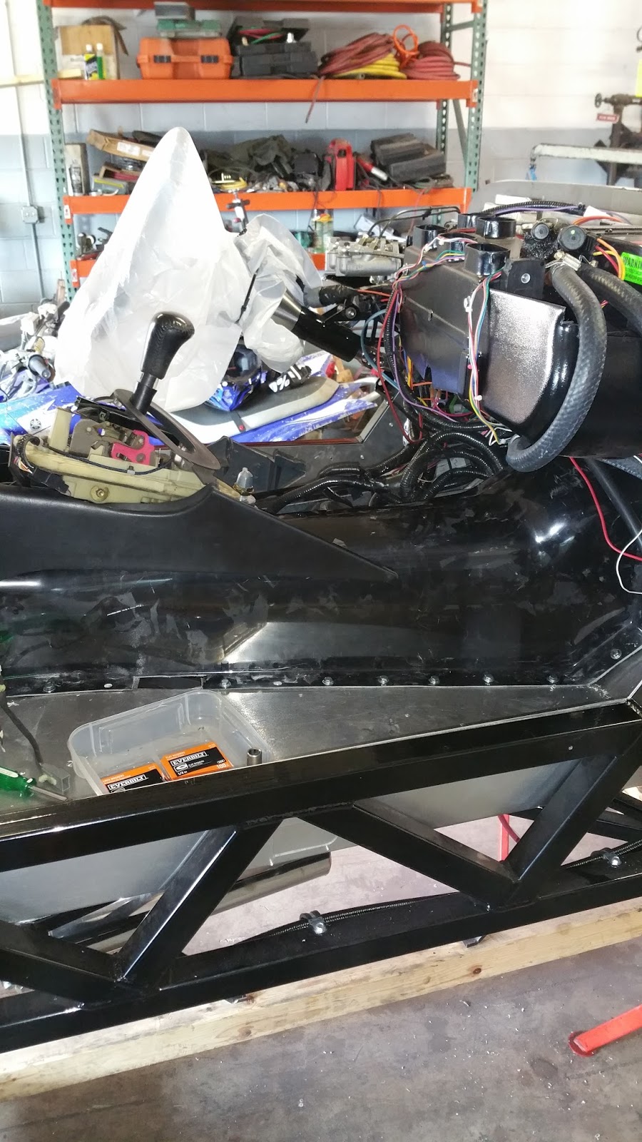
We also installed the transmission tunnel, the accelerator pedal area is tight - we may have to move the brake pedal - we will test it out once we have the seats in.


Lots of wire loom in front of the shifter  - our plan is to fabricate a center console with a tablet ( like a Tesla, only android) to cover this up, house the speakers and the air con controls and have the battery disconnect switch in a compartment that covers. We are working out all the wiring for that now.

Monday, February 6, 2017

Routing the Coolant Hoses

February 6, 2017

The engine cooling system on our engine is not standard. Let me explain. Most engines have a thermostat that keeps the water in the engine circulating until it gets to between 175F and 200F degrees. Then it opens up and the coolant flows from the top of the engine into the upper radiator hose to be cooled. This is so that in cold weather the engine can warm up quicker for optimal performance, better emissions, and fuel economy while running below 200 degrees. In most systems, all the engine coolant runs through a single output through the thermostat housing and into the radiator. In our engine, there are two outlets that then are routed to a 4-way union that houses the thermostat.


Since our radiator is in a different location and our overflow tank is not set up to be large and above the radiator and 3 different hose sizes, this setup is cumbersome and difficult to recreate. After a few days of trying to make something work out without success, my brother Larry postulated the question - why have a thermostat? After some discussion we determined we don't need one. The car will hardly if ever see engine temperature below 50 degrees - no winter salt and snow driving, so the amount of time warming up is minimal. This made the job a bit easier, but now we needed to replace that 4-way union with a 3-way with two 1.5 inch hose inlets and one 1.25 inch inlet. No standard part exists that we could find ( a week of searching), so we decided to make our own from copper plumbing parts. Also a bit tricky since most copper plumbing installations don't mix pipe diameter sizes.  After a few trips to different stores and a few designs and some flexible hoses, we have it figured out. We started with a dry build and then soldered things up. Now we will have to see if it leaks or not once we fire up the engine again.


Friday, February 3, 2017

Mods - Not Those British Gangs in the 60s

February 3, 2017

We weren't happy with the way a few things were panning out and decided to spend the time modifying them so we would feel better about the build.
The first was the drive shaft. There were two things bugging us. First, the yoke ( the end that goes in the transmission) had a lot of play and second because we moved the engine forward a few inches to get better clearance at the firewall, the yoke was exposed more than usual. 


So we went ahead and used the yoke from the Lincoln drive shaft, which we knew would have a lot less play and would marry to the seal better (yellow ring in the picture) and we sent the drive shaft after some measuring to a drive shaft fabricator to lengthen and rebalance it. Now it feels right - no play and looks normal (about an inch of visible yoke)  at the transmission. I have also included a photo of the difference in length of the old Lincoln drive shaft (minus a yoke) and the new one.


The second mod we did concerned heat transfer from the exhaust system into the passenger compartment. After installing the mufflers and thinking about the very thin sheet-metal floor we were about to install, it was becoming obvious that we would have a heat problem and possibly melting carpet. We do plan to put some heat and sound material on the floor under the carpet, but it still concerned us. So we did two more things to help mitigate the heat transfer. One is we fabricated some heat shields that will cover the mufflers and deflect the radiant heat away from the floor. We also lined the underside floor panel with the same heat shield fabric we used on the firewall. It's rated to 2000 degrees Fahrenheit. Mufflers run about 300-500 degrees so we should be better with these modifications.

The heat shields


the underside of the floor panel with the heat fabric

with the heat shield mounted, it's cut to fit around the frame x bracing

Now the floor is installed