Friday, February 3, 2017

Mods - Not Those British Gangs in the 60s

February 3, 2017

We weren't happy with the way a few things were panning out and decided to spend the time modifying them so we would feel better about the build.
The first was the drive shaft. There were two things bugging us. First, the yoke ( the end that goes in the transmission) had a lot of play and second because we moved the engine forward a few inches to get better clearance at the firewall, the yoke was exposed more than usual. 


So we went ahead and used the yoke from the Lincoln drive shaft, which we knew would have a lot less play and would marry to the seal better (yellow ring in the picture) and we sent the drive shaft after some measuring to a drive shaft fabricator to lengthen and rebalance it. Now it feels right - no play and looks normal (about an inch of visible yoke)  at the transmission. I have also included a photo of the difference in length of the old Lincoln drive shaft (minus a yoke) and the new one.


The second mod we did concerned heat transfer from the exhaust system into the passenger compartment. After installing the mufflers and thinking about the very thin sheet-metal floor we were about to install, it was becoming obvious that we would have a heat problem and possibly melting carpet. We do plan to put some heat and sound material on the floor under the carpet, but it still concerned us. So we did two more things to help mitigate the heat transfer. One is we fabricated some heat shields that will cover the mufflers and deflect the radiant heat away from the floor. We also lined the underside floor panel with the same heat shield fabric we used on the firewall. It's rated to 2000 degrees Fahrenheit. Mufflers run about 300-500 degrees so we should be better with these modifications.

The heat shields


the underside of the floor panel with the heat fabric

with the heat shield mounted, it's cut to fit around the frame x bracing

Now the floor is installed


Friday, January 20, 2017

Punch List

January 20, 2017

We are trying to get to the go kart phase - driving it without the body by the time we head out to South East Asia and Spring Training mid-Feb. Our punch list is quite large, but we are making progress. Here are some of the thing we are focused on

- Fuel lines
- Exhaust
- Air conditioning/heating 
- Radiator
- Cockpit floor, trans tunnel
- Seats and seat belts
- Steering wheel
- Bleed the brakes and install new brake fluid lines for the fluid reservoir
- Shifter
- Accelerator pedal
- Grease, oil, and fluids
- Finish electrical battery feeds

To that end, we have started on a few of these.


Exhaust Mufflers Installed

Aircon Evaporator and Heater Blower Motor
Aircon Drier and Firewall Hose Fittings
Black Braided Line is Fuel Line


Monday, January 9, 2017

Wiring 101

January 9, 2017

We have completed the wiring transplant with success! If we knew then what we know now....  this is the epiphany of where all the hours have gone and the rationalization of at least I learned something I didn't know. 

It's worth taking a bit of blog space and showing what we started out with and the steps along the way. 


Almost a year ago, mid-February 2017, we bought a 1997 Lincoln Mark VIII as a donor car for our engine, transmission and rear end for $1600 cash. We would then sell the rest and maybe try to get our money back, making the parts we use free - albeit with a ton of effort.

deconstruction under way

Finally  March 3, 2016, all the wire is out and intact.


By March 15, 2016, we have the engine and the wiring out of the car and on the floor running -we have successfully removed the donor organs!


For the next few months, we cut out wires we know we will not need for example the heated seats, radio and amplifier, power door locks and windows, headlights and tail lights, ...

Now we are left with mostly the wires we need so we can install the engine onto the frame of the 1933 Ford hot rod we are building.


May 15, 2016, the engine goes in  - it will come out a few more times, but at this point; we are thinking it's in for the final time - what little did we know. It will come out twice more to move it forward and eliminate the donor car exhaust headers that don't fit. 


We then go on to zip tie the wires we have  into more organized looms


While looking at the wires we had left, there was still an opportunity to remove more. You can see in the photo above some very big connectors, and the under the hood fuse box. We started to eliminate those and get it running on the ground once again.


Here is the final wire pared down from the original donor car by over 50 pounds.


then wrapped up for final install


some photos of it installed and running in the 1933 Ford Frame


Thursday, January 5, 2017

On Second Thought

January 5, 2017


As mentioned in the last post, we have been spending a month of Sundays re-doing some of the work we completed. After completing the placement of the battery disconnect and remote charging terminals in the trunk, my brother Larry had a what are you thinking moment and brought to light that we were installing open electrical connections right next to the fuel tank. If we were in a rear end accident, it could cause a ruptured fuel tank and a subsequent spark from the battery terminals - Ford Pinto in action (a famous engineering failure in the 1970's). So we are in the process of removing it and repositioning it in the engine compartment on the firewall. That leaves the fuel pump computer which we will mount away from the tank near the wheel well where it was at in the donor Lincoln Mark VIII.

The black box in the background is the fuel tank
red and black posts are battery connections

As you can see a real possibility, not sure how I missed this - glad Larry is paying attention. As we are building this car we are reading the many forum posts and build blogs. There are quite a few who put electronics and even the battery in the trunk. It's appealing because there is little room for it anywhere else on the car. They also don't want it taking away from the engine compartment wow factor. We will choose safety everytime over wow factor.


Thursday, December 29, 2016

Mulligan

December 29, 2016


It's been a month of work and now a lot of do-overs. Let me get into it.

Over a month ago we felt pretty good since we got the engine running on the floor and we were getting ready to lower the engine onto the frame. Well, that all went pear shaped. For the past week and a half after getting all the wiring connected to the engine, we did get the engine to fire up, but only for 3 seconds at a time, unless we sprayed ether into the manifold in which it could run as long as we were spraying it - so it was getting spark. So debugging and wild diagnosis began. We thought it might be a fuel problem, so even though we could hear the fuel pump running in the fuel tank, we put a fuel pressure gauge on the fuel rails. With the key on we had  40lbs of pressure and over the 3 seconds it went down to 25-30lbs, enough to keep it running, but still not a positive sign, especially as we were gunning the throttle.

We then thought we might have a vacuum problem, so we went around hooking up all the vacuum lines - no change. 

All the time we were doing research on-line, was it the pats( passive anti-theft) system, the O2 sensors, were there any broken wires or bad connections, how long did the engine computer need to be disconnected so it could reset, was there a kink in the fuel lines, a rag left in the tank, the air intake MAF( mass air flow) sensor, or the IMRC ( intake manifold runner control).  

We hooked up the SCIL(steering column, ignition, and lighting computer) and donor car ignition key to see if it was pats, still no change, so we were confident that the anti-theft system was not causing the no-run condition. We also knew the hardest part of getting the engine working is getting it to run and we had it running for 3 secs every time. 

It was classic debug and diagnosis; wild theories were brought up, laughed about and then checked out as we were running out of ideas.

Since the signature of the problem had something killing the engine, we started to think back to it running on the floor and started to realize that maybe we have had this problem for a while. We would only let it run on the floor for a few seconds for a number of reasons including not wanting the engine to get damaged (rolling over, overheating); since it was running rich, we didn't want to poison ourselves. There was no reason to run it more - we figured if we got it to run 3 seconds why was 5 seconds better, until we now couldn't get it to run for more.

The signature of this problem had us go back to pats and look to see if we were missing something. We took apart the SCIL and our assumption that since there were four connectors on the SCIL box  - two for each circuit board. We figured that each circuit board had it's own power supply and since all the anti-theft signals were on the bottom circuit board, we thought that was the only circuit board needing to be powered - wrong. We took it apart, and there were a couple of ribbon cables connecting both boards, so we hooked up all the power to the SCIL box. We also noticed there is an anti-theft indicator light output and a hood and door alarm input. We hooked all these up  - still not working, but we connected a test light to the anti-theft indicator light wire and it flashed indicating the alarm was being set off. 


The SCIL box on the right, the PCM on the left
all the red power wires to the SCIL box
the test light in the middle 


We relooked at the service manual to figure out what does what to make the pats system work. It's a bit complicated as there are 5 different set ups depending on the make and model. The system we have was only produced for the 1997 and 1998 Lincoln MarkVIII - this limits the collective knowledge on the system and ways around it. For example this is the only system where you need two programmed keys to make another one, unfortunately for us, we only have 1 key limiting our options if the key is the issue. As an aside the reason for 2 keys is that the engineers were concerned that if you valet the car the attendant could go get a copy with just one, with this requirement the owner would be the only one with 2 keys to have a copy made.

Here is how the system works. The key has a chip and magnetic exciter embedded in the hard plastic of the key. The ignition switch has a round antenna ring that is wired in a loop to the SCIL computer. When the key is in start mode the SCIL sends a signal and within 800 milliseconds a J1850 PWM code is sent back from the key to the SCIL. The SCIL compares it to the programmed value of the key. If it's the same everything is cool, if not a kill the engine signal goes to PCM( powertrain computer module). With the anti-theft light acknowledging the event, we knew the SCIl was sending the kill signal, but why?

We then hooked up the OBD (on-board diagnostics) connector and then saw what repair codes the PCM was collecting. It triggered code P1260, which is Theft detected vehicle immobilized. We then tried to isolate it to the key, hood latch or door lock, problem was we needed to turn the key for it to trigger - no luck here. We went through the service manual diagnostic trees and most of them had you replacing the key  - something we couldn't do because we needed two keys to make a new one, or replacing the SCIL ( hard to find with a key). Since we were only using the donor car ignition switch to fool the system that the key was on, we started to take it apart. (BTW we use a simple ignition switch to start the car.We found that it did not need any power for the ring antenna to work with the key, so on a lark, we removed the ring antenna and placed the key right in it - see the picture below. 


The white part is the ring antenna, the black part has the embedded chip


At this point, it started and works consistently and reliably - hallelujah a holiday miracle. 


There are a few other mulligans (do-overs), but we will save that for the next blog post.

Thursday, December 22, 2016

Punch List - Getting Ready For Wiring Installation

December 22, 2016

We are looking at using the days around Christmas to use for installing the wiring. Therefore the last week or so we have been cleaning up and completing tasks all around the car. David and my brother Larry have been helping out with most of it.

Here are some of the tasks we completed

- Installed horns
- Built trunk electrical panel  - This has the remote battery terminals ( for easy charging or jump starting - with the battery mounted below the fuel tank with little clearance this is a must), the fuel pump computer and a battery cutoff switch (this is used for disconnecting the battery when the car is in storage)

hard to get at red battery 


two remote battery posts, disconnect switch, and fuel pump driver computer


We added the plastic cover so that we could use the top shelf in the trunk without worrying about shorting anything out - it's just an inverted Tupperware storage container.

- Modified exhaust headers - Even though we went with the smaller aftermarket headers, they are still too big for the engine to seat correctly on the motor mount brackets. David was able to heat them up, bend them with a hammer so they cleared the mounts and now the engine is properly resting on the mounts and the headers are installed.


- Cleaned and installed the air conditioning compressor
- Installed rear brake lines
- Added engine ground strap


- Getting the wiring ready - Larry continues to remove unnecessary wires cleaning up the loom


- Installed a new transmission mount - Since we moved the engine forward 2.5 inches, the kit mount did not line up correctly, so we found a mustang one that worked


We are ready for the weekend to get the wiring squared away, our goal is getting the engine running. Of course, we will need to hook up the fuel lines and the radiator 

Sunday, December 11, 2016

Lots of work on the Hot Rod, not so much on the blog

December 11, 2016

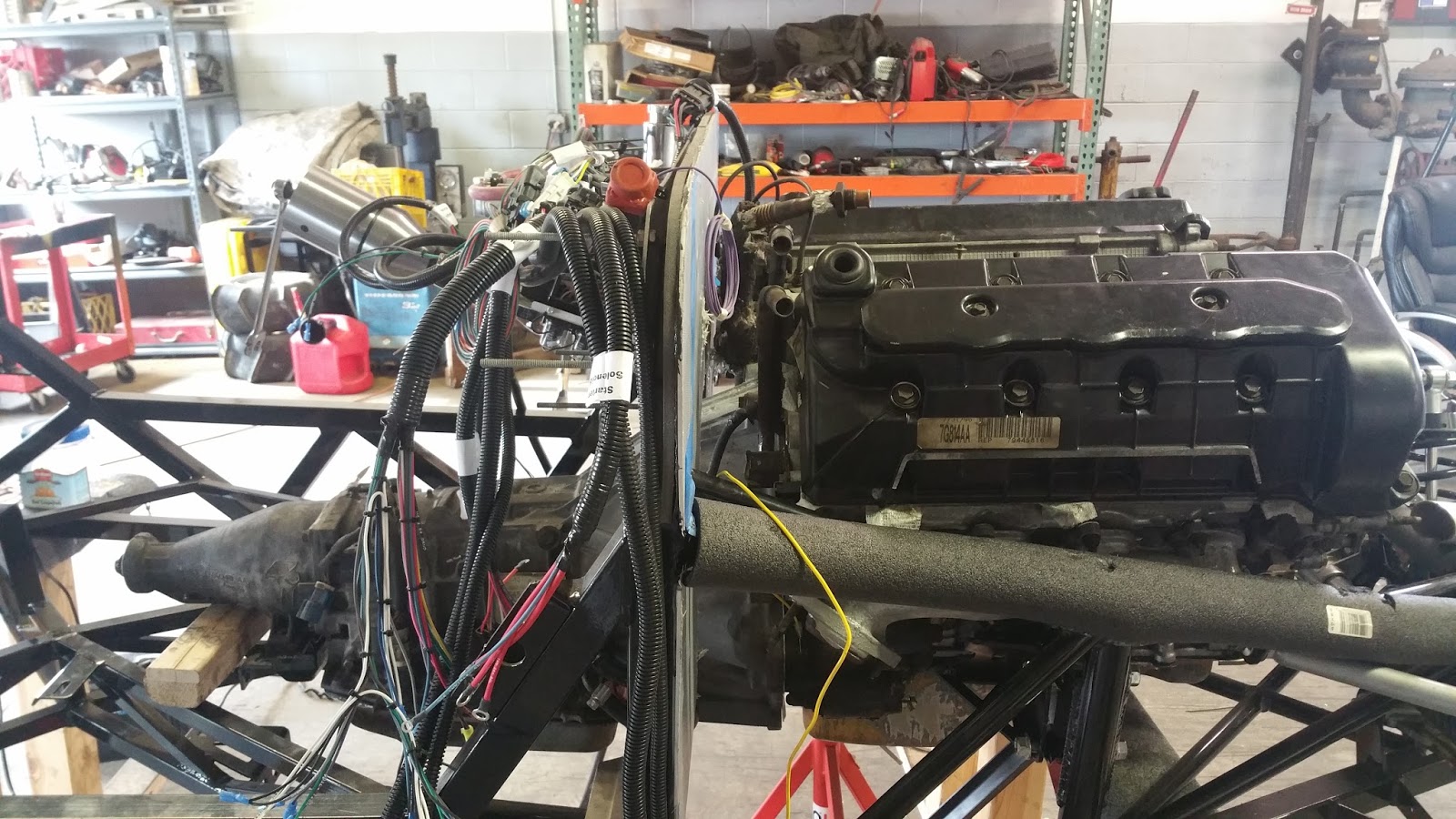
It's been a busy couple of weeks working on the hot rod and we have made some significant progress. The highlight is getting the engine in for the final time, which was quite an effort and made us change some of our strategy regarding the build. Let me explain how things went and how it affected the build.

We spent a number of hours going one last time through the wiring to eliminate as many unnecessary wires; getting down to just what runs the engine, fuel pump and the computer. After all the work we did here it might of made more sense to just start with no wires and use the wiring diagrams to wire everything up.  We still have work to do to make the wires now fit the frame we have, but the finish line is in sight.


The wiring is now on a table, the 2x4s are a layout of the dimensions and placement of key components like the fuel pump, starter and firewall. We will now spend time making the wires on the table fit to this 2x4 skeleton.

We were also not happy with the last placement of the engine as it was right up against the fire wall (we were worried about heat transfer into the cabin) and we didn't have room for the IRMC (Intake Manifold Runner Control) - this  operates a butterfly valve in the intake manifold. We also did not have room for the EGR(Exhaust Gas Recirculator) pipe return from the exhaust header to the intake manifold. The purpose of both of these is to optimize the air/fuel ratio for best fuel economy and drivability. These both play a part in passing emission testing and our plan was to keep all of the emissions controls in case the car would be sold in a state which would require it for daily driving. In Illinois, our hot rod falls under the classifications of street rod custom vehicle; and doesn't require passing emission testing, so although not required, it was on our nice to have list, and we were proceeding with this plan.

So we needed to make room and move the engine forward. This required us to modify the frame motor mount brackets. Jake did most of the work here using the torch to add an additional mounting hole two inches forward. This was about all we could bring it forward since the AC air compressor would then hit the frame in the front, and we only had so much play in the length of the drive shaft to accommodate a longer path between the engine/transmission and differential in the rear end.


Once we had the new position on the motor mount frame mounting brackets we added the IRMC, EGR exhaust tube and the exhaust headers to the engine before we lowered it in. After about an hour of lifting and lowering the engine, snaking it's way into position, we had it in and things were looking good. David started to begin the process of putting things back on the engine. We also spent some time cleaning and painting a few of the parts we were installing so the engine could look as best as possible. 


We then moved on to installing the fuel tank, the transmission mounts and the drive shaft. 


For the fuel tank we had to place an aluminum panel and we did this using an aircraft system tool called Clecos for rivet placement. Whenever you look at an airplane and see the precision mounting of panels using rivets, they use this system to hold down sections of panels so every hole they drill does not move the panel, once all the holes are drilled we could remove these Celcos (temp rivets) and then apply construction adhesive and rivets. We also added a rubber mat under the fuel tank to help dampen vibration.


We ran into some trouble with the transmission mounts and driveshaft. The transmission will need a spacer and the supplied kit spacers are just too flimsy in our opinion, so we will fabricate a spacer block, also since we moved the engine up 2 inches, we need to modify the mount as well.  As we tried to make the mount work we discovered that the motor mount alignment pins just missed the hole and the engine was not properly seated on the frame mounting brackets, even though we had the hold down bolt go through the adjacent hole. When looking at it further, the alignment pin fell right on the vertical support, so we had to remove the alignment pins requiring us to lift the engine up a half a foot while we did this. Of course this required us to take off the intake manifold once again  - a bit frustrating, but an hour later we had the engine seated properly and the intake manifold and injector wiring harness installed.  

Now that the engine was properly seated we discovered another issue. Although we had clearance for the IRMC and EGR pipe, the driver side exhaust header was binding on the steering shaft and frame. We removed a heat shield on the header, a small improvement, but it was still binding. After much heated discussion and the I told you we should have never worried about having the car pass emissions reminders, we decided to change out the headers to ones without the embedded catalytic converter. These headers have a reduced profile so the huge engine can fit into hot rod engine bays. Also most hot rodders get rid of emission so they can boost performance. Luckily we had bought some of these so we could swap out the original headers with these new chrome ones. We solved the problem, but we gave up on our 50 state sales strategy. 


Old Header
New Header